
A three-phase asynchronous motor is a type of induction motor that is powered by simultaneously connecting a 380V three-phase AC current (phase difference of 120 degrees). Due to the fact that the rotor and stator rotating magnetic field of a three-phase asynchronous motor rotate in the same direction and at different speeds, there is a slip rate, so it is called a three-phase asynchronous motor.
The speed of the rotor of a three-phase asynchronous motor is lower than the speed of the rotating magnetic field. The rotor winding generates electromotive force and current due to relative motion with the magnetic field, and interacts with the magnetic field to generate electromagnetic torque, achieving energy transformation.
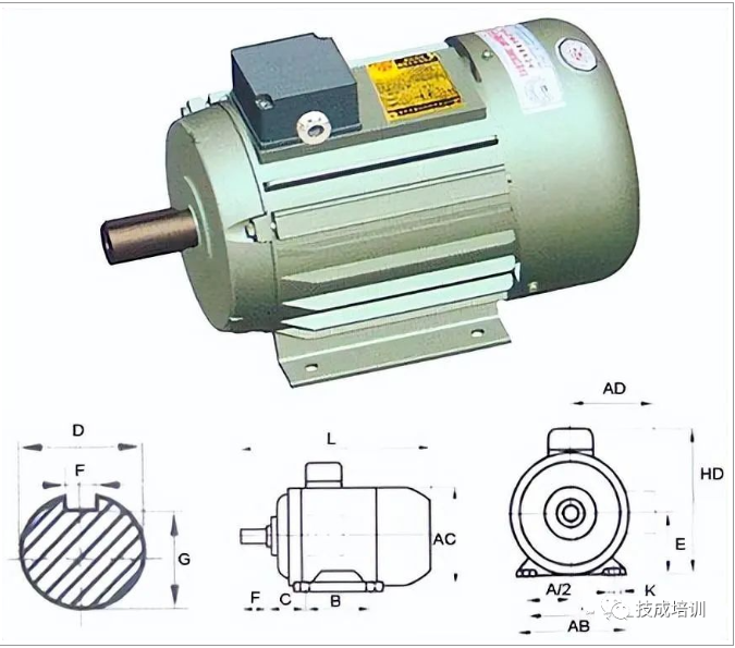
Compared with single-phase asynchronous motors, three-phase asynchronous motors have better operating performance and can save various materials.
According to the different rotor structures, three-phase asynchronous motors can be divided into cage type and wound type
The asynchronous motor with cage rotor has a simple structure, reliable operation, light weight, and low price, which has been widely used. Its main drawback is the difficulty in speed regulation.
The rotor and stator of a wound three-phase asynchronous motor are also equipped with three-phase windings and connected to an external rheostat through slip rings, brushes. Adjusting the resistance of the rheostat can improve the starting performance of the motor and adjust the speed of the motor.
The working principle of three-phase asynchronous motor
When symmetrical three-phase alternating current is applied to the three-phase stator winding, a rotating magnetic field is generated that rotates clockwise along the inner circular space of the stator and rotor at synchronous speed n1.
Since the rotating magnetic field rotates at n1 speed, the rotor conductor is stationary at the beginning, so the rotor conductor will cut the stator rotating magnetic field to generate induced electromotive force (the direction of the induced electromotive force is determined by the Right-hand rule).
Due to the short circuiting of the rotor conductor at both ends by a short-circuit ring, under the action of the induced electromotive force, the rotor conductor will generate an induced current that is basically in the same direction as the induced electromotive force. The current carrying conductor of the rotor is subjected to electromagnetic force in the stator magnetic field (the direction of the force is determined using the left-hand rule). Electromagnetic force generates electromagnetic torque on the rotor shaft, driving the rotor to rotate in the direction of the rotating magnetic field.
Through the above analysis, it can be concluded that the working principle of an electric motor is as follows: when the three-phase stator windings of the motor (each with a 120 degree electrical angle difference) are fed with three-phase symmetrical alternating current, a rotating magnetic field is generated, which cuts the rotor winding and generates induced current in the rotor winding (the rotor winding is a closed circuit). The current carrying rotor conductor will generate electromagnetic force under the action of the stator rotating magnetic field, Thus, electromagnetic torque is formed on the motor shaft, driving the motor to rotate in the same direction as the rotating magnetic field.
Wiring diagram of three-phase asynchronous motor
Basic wiring of three-phase asynchronous motors:
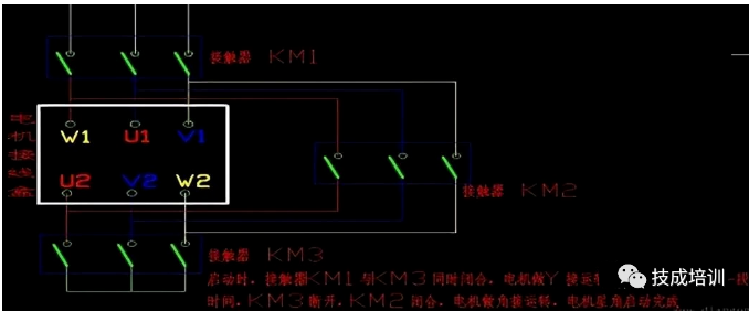
The six wires from the winding of a three-phase asynchronous motor can be divided into two basic connection methods: delta delta connection and star connection.
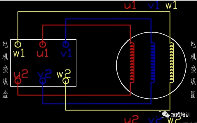
Six wires=three motor windings=three head ends+three tail ends, with a multimeter measuring the connection between the head and tail ends of the same winding, i.e. U1-U2, V1-V2, W1-W2.
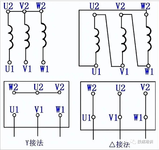
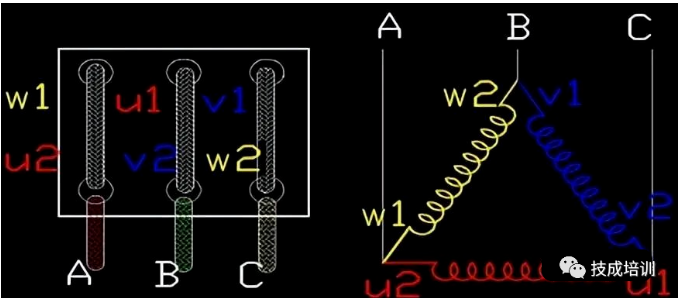
1. Triangle delta connection method for three-phase asynchronous motors
The triangle delta connection method is to connect the heads and tails of three windings in sequence to form a triangle, as shown in the figure:
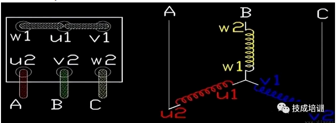
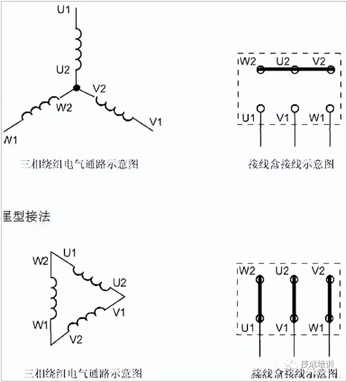
2. Star connection method for three-phase asynchronous motors
The star connection method is to connect the tail or head ends of three windings, and the other three wires are used as power connections. Connection method as shown in the figure:
Explanation of the Wiring Diagram of Three Phase Asynchronous Motor in Figures and Text
Three phase motor junction box
When the three-phase asynchronous motor is connected, the connection method of the connecting piece in the junction box is as follows:
When the three-phase asynchronous motor is corner connected, the connection method of the junction box connection piece is as follows:
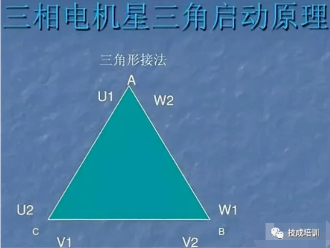
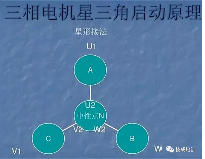
There are two connection methods for three-phase asynchronous motors: star connection and triangle connection.
Triangulation method
In winding coils with the same voltage and wire diameter, the star connection method has three times less turns per phase (1.732 times) and three times less power than the triangle connection method. The connection method of the finished motor has been fixed to withstand a voltage of 380V and is generally not suitable for modification.
The connection method can only be changed when the three-phase voltage level is different from the normal 380V. For example, when the three-phase voltage level is 220V, changing the star connection method of the original three-phase voltage 380V to the triangle connection method can be applicable; When the three-phase voltage level is 660V, the original three-phase voltage 380V delta connection method can be changed to star connection method, and its power remains unchanged. Generally, low-power motors are star connected, while high-power motors are delta connected.
At rated voltage, a delta connected motor should be used. If it is changed to a star connected motor, it belongs to reduced voltage operation, resulting in a decrease in motor power and starting current. When starting a high-power motor (delta connection method), the current is very high. In order to reduce the impact of the starting current on the line, step-down starting is generally adopted. One method is to change the original delta connection method to star connection method for starting. After the star connection method is started, it is converted back to delta connection method for operation.
Wiring diagram of three-phase asynchronous motor
Physical diagram of forward and reverse transfer lines for three-phase asynchronous motors:
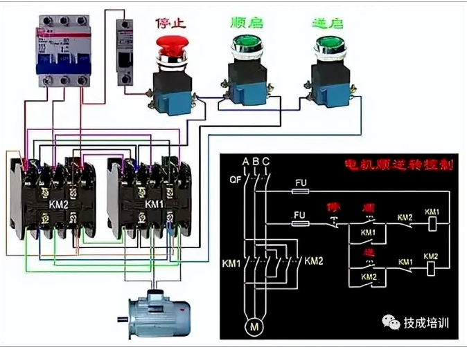
To achieve forward and reverse control of a motor, any two phases of its power supply can be adjusted relative to each other (we call it commutation). Usually, the V phase remains unchanged, and the U phase and W phase are adjusted relative to each other. In order to ensure that the phase sequence of the motor can be reliably exchanged when two contactors act, the wiring should be consistent at the upper port of the contact, and the phase should be adjusted at the lower port of the contactor. Due to the phase sequence swapping of the two phases, it is necessary to ensure that the two KM coils cannot be powered on at the same time, otherwise serious phase to phase short circuit faults may occur. Therefore, interlocking must be adopted.
For safety reasons, a double interlocking forward and reverse control circuit with button interlocking (mechanical) and contactor interlocking (electrical) is often used; By using button interlocking, even if the forward and reverse buttons are pressed simultaneously, the two contactors used for phase adjustment cannot be powered on simultaneously, mechanically avoiding phase to phase short circuits.
In addition, due to the interlocking of the applied contactors, as long as one of the contactors is powered on, its long closed contact will not close. This way, in the application of mechanical and electrical dual interlocking, the power supply system of the motor cannot have phase to phase short circuits, effectively protecting the motor and avoiding accidents caused by phase to phase short circuits during phase modulation, which can burn the contactor.
Post time: Aug-07-2023


