
1. Introduction to Electric Motors
An electric motor is a device that converts electrical energy into mechanical energy. It utilizes an energized coil (i.e. stator winding) to generate a rotating magnetic field and act on the rotor (such as a squirrel cage closed aluminum frame) to form a magnetoelectric rotational torque.
Electric motors are divided into DC motors and AC motors according to the different power sources used. Most of the motors in the power system are AC motors, which can be synchronous motors or asynchronous motors (the stator magnetic field speed of the motor does not maintain synchronous speed with the rotor rotation speed).
An electric motor mainly consists of a stator and a rotor, and the direction of the force acting on the energized wire in the magnetic field is related to the direction of the current and the direction of the magnetic induction line (magnetic field direction). The working principle of an electric motor is the effect of a magnetic field on the force acting on the current, causing the motor to rotate.
2. Division of electric motors
① Classification by working power supply
According to the different working power sources of electric motors, they can be divided into DC motors and AC motors. AC motors are also divided into single-phase motors and three-phase motors.
② Classification by structure and working principle
Electric motors can be divided into DC motors, asynchronous motors, and synchronous motors according to their structure and working principle. Synchronous motors can also be divided into permanent magnet synchronous motors, reluctance synchronous motors, and hysteresis synchronous motors. Asynchronous motors can be divided into induction motors and AC commutator motors. Induction motors are further divided into three-phase asynchronous motors and shaded pole asynchronous motors. AC commutator motors are also divided into single-phase series excited motors, AC DC dual purpose motors, and repulsive motors.
③ Classified by startup and operation mode
Electric motors can be divided into capacitor started single-phase asynchronous motors, capacitor operated single-phase asynchronous motors, capacitor started single-phase asynchronous motors, and split phase single-phase asynchronous motors according to their starting and operating modes.
④ Classification by purpose
Electric motors can be divided into driving motors and control motors according to their purpose.
Electric motors for driving are further divided into electric tools (including drilling, polishing, polishing, slotting, cutting, and expanding tools), electric motors for household appliances (including washing machines, electric fans, refrigerators, air conditioners, recorders, video recorders, DVD players, vacuum cleaners, cameras, electric blowers, electric shavers, etc.), and other general small mechanical equipment (including various small machine tools, small machinery, medical equipment, electronic instruments, etc.).
Control motors are further divided into stepper motors and servo motors.
⑤ Classification by rotor structure
According to the structure of the rotor, electric motors can be divided into cage induction motors (formerly known as squirrel cage asynchronous motors) and wound rotor induction motors (formerly known as wound asynchronous motors).
⑥ Classified by operating speed
Electric motors can be divided into high-speed motors, low-speed motors, constant speed motors, and variable speed motors according to their operating speed.
⑦ Classification by protective form
a. Open type (such as IP11, IP22).
Except for the necessary support structure, the motor does not have special protection for the rotating and live parts.
b. Closed type (such as IP44, IP54).
The rotating and live parts inside the motor casing need necessary mechanical protection to prevent accidental contact, but it does not significantly hinder ventilation. Protective motors are divided into the following types according to their different ventilation and protection structures.
ⓐ Mesh cover type.
The ventilation openings of the motor are covered with perforated coverings to prevent the rotating and live parts of the motor from coming into contact with external objects.
ⓑ Drip resistant.
The structure of the motor vent can prevent vertically falling liquids or solids from directly entering the interior of the motor.
ⓒ Splash proof.
The structure of the motor vent can prevent liquids or solids from entering the interior of the motor in any direction within a vertical angle range of 100 °.
ⓓ Closed.
The structure of the motor casing can prevent the free exchange of air inside and outside the casing, but it does not require complete sealing.
ⓔ Waterproof.
The structure of the motor casing can prevent water with a certain pressure from entering the interior of the motor.
ⓕ Watertight.
When the motor is immersed in water, the structure of the motor casing can prevent water from entering the interior of the motor.
ⓖ Diving style.
The electric motor can operate in water for a long time under rated water pressure.
ⓗ Explosion proof.
The structure of the motor casing is sufficient to prevent the gas explosion inside the motor from being transmitted to the outside of the motor, causing the explosion of combustible gas outside the motor. Official account “Mechanical Engineering Literature”, engineer’s gas station!
⑧ Classified by ventilation and cooling methods
a. Self cooling.
Electric motors rely solely on surface radiation and natural air flow for cooling.
b. Self cooled fan.
The electric motor is driven by a fan that supplies cooling air to cool the surface or interior of the motor.
c. He fan cooled.
The fan supplying cooling air is not driven by the electric motor itself, but is independently driven.
d. Pipeline ventilation type.
Cooling air is not directly introduced or discharged from the outside of the motor or from the inside of the motor, but is introduced or discharged from the motor through pipelines. Fans for pipeline ventilation can be self fan cooled or other fan cooled.
e. Liquid cooling.
Electric motors are cooled with liquid.
f. Closed circuit gas cooling.
The medium circulation for cooling the motor is in a closed circuit that includes the motor and the cooler. The cooling medium absorbs heat when passing through the motor and releases heat when passing through the cooler.
g. Surface cooling and internal cooling.
The cooling medium that does not pass through the inside of the motor conductor is called surface cooling, while the cooling medium that passes through the inside of the motor conductor is called internal cooling.
⑨ Classification by installation structure form
The installation form of electric motors is usually represented by codes.
The code is represented by the abbreviation IM for international installation,
The first letter in IM represents the installation type code, B represents horizontal installation, and V represents vertical installation;
The second digit represents the feature code, represented by Arabic numerals.
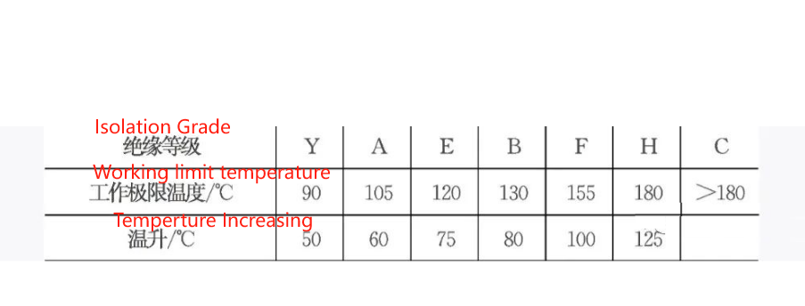
⑩ Classification by insulation level
A-level, E-level, B-level, F-level, H-level, C-level. The insulation level classification of motors is shown in the table below.
⑪ Classified according to rated working hours
Continuous, intermittent, and short-term working system.
Continuous Duty System (SI). The motor ensures long-term operation under the rated value specified on the nameplate.
Short time working hours (S2). The motor can only operate for a limited period of time under the rated value specified on the nameplate. There are four types of duration standards for short-term operation: 10min, 30min, 60min, and 90min.
Intermittent working system (S3). The motor can only be used intermittently and periodically under the rated value specified on the nameplate, expressed as a percentage of 10 minutes per cycle. For example, FC=25%; Among them, S4 to S10 belong to several intermittent operating working systems under different conditions.
9.2.3 Common faults of electric motors
Electric motors often encounter various faults during long-term operation.
If the torque transmission between the connector and the reducer is large, the connecting hole on the flange surface shows severe wear, which increases the fit gap of the connection and leads to unstable torque transmission; The wear of the bearing position caused by damage to the motor shaft bearing; Wear between shaft heads and keyways, etc. After the occurrence of such problems, traditional methods mainly focus on repair welding or machining after brush plating, but both have certain drawbacks.
The thermal stress generated by high temperature repair welding cannot be completely eliminated, which is prone to bending or fracture; However, brush plating is limited by the thickness of the coating and is prone to peeling, and both methods use metal to repair the metal, which cannot change the “hard to hard” relationship. Under the combined action of various forces, it will still cause re wear.
Contemporary Western countries often use polymer composite materials as repair methods to address these issues. The application of polymer materials for repair does not affect welding thermal stress, and the repair thickness is not limited. At the same time, the metal materials in the product do not have the flexibility to absorb the impact and vibration of the equipment, avoid the possibility of re wear, and extend the service life of equipment components, saving a lot of downtime for enterprises and creating huge economic value.
(1) Fault phenomenon: The motor cannot start after being connected
The reasons and handling methods are as follows.
① Stator winding wiring error – check the wiring and correct the error.
② Open circuit in stator winding, short circuit grounding, open circuit in winding of wound rotor motor – identify the fault point and eliminate it.
③ Excessive load or stuck transmission mechanism – check the transmission mechanism and load.
④ Open circuit in the rotor circuit of a wound rotor motor (poor contact between the brush and the slip ring, open circuit in the rheostat, poor contact in the lead, etc.) – identify the open circuit point and repair it.
⑤ The power supply voltage is too low – check the cause and eliminate it.
⑥ Power supply phase loss – check the circuit and restore the three-phase.
(2) Fault phenomenon: Motor temperature rise too high or smoking
The reasons and handling methods are as follows.
① Overloaded or started too frequently – reduce the load and reduce the number of starts.
② Phase loss during operation – check the circuit and restore the three-phase.
③ Stator winding wiring error – check the wiring and correct it.
④ The stator winding is grounded, and there is a short circuit between turns or phases – identify the grounding or short circuit location and repair it.
⑤ Cage rotor winding broken – replace the rotor.
⑥ Missing phase operation of wound rotor winding – identify the fault point and repair it.
⑦ Friction between stator and rotor – Check bearings and rotor for deformation, repair or replace.
⑧ Poor ventilation – check if the ventilation is unobstructed.
⑨ Voltage too high or too low – Check the cause and eliminate it.
(3) Fault phenomenon: Excessive motor vibration
The reasons and handling methods are as follows.
① Unbalanced rotor – leveling balance.
② Unbalanced pulley or bent shaft extension – check and correct.
③ The motor is not aligned with the load axis – check and adjust the axis of the unit.
④ Improper installation of the motor – check the installation and foundation screws.
⑤ Sudden overload – reduce the load.
(4)Fault phenomenon: Abnormal sound during operation
The reasons and handling methods are as follows.
① Friction between stator and rotor – Check bearings and rotor for deformation, repair or replace.
② Damaged or poorly lubricated bearings – replace and clean the bearings.
③ Motor phase loss operation – check the open circuit point and repair it.
④ Blade collision with casing – check and eliminate faults.
(5) Fault phenomenon: The speed of the motor is too low when under load
The reasons and handling methods are as follows.
① The power supply voltage is too low – check the power supply voltage.
② Excessive load – check the load.
③ Cage rotor winding broken – replace the rotor.
④ Poor or disconnected contact of one phase of the winding rotor wire group – check the brush pressure, the contact between the brush and the slip ring, and the rotor winding.
(6) Fault phenomenon: The motor casing is live
The reasons and handling methods are as follows.
① Poor grounding or high grounding resistance – Connect the ground wire according to regulations to eliminate poor grounding faults.
② Windings are damp – undergo drying treatment.
③ Insulation damage, lead collision – Dip paint to repair insulation, reconnect leads. 9.2.4 Motor operating procedures
① Before disassembly, use compressed air to blow off the dust on the surface of the motor and wipe it clean.
② Select the working location for motor disassembly and clean the on-site environment.
③ Familiar with the structural characteristics and maintenance technical requirements of electric motors.
④ Prepare the necessary tools (including special tools) and equipment for disassembly.
⑤ In order to further understand the defects in the operation of the motor, an inspection test can be conducted before disassembly if conditions permit. To this end, the motor is tested with a load, and the temperature, sound, vibration, and other conditions of each part of the motor are checked in detail. The voltage, current, speed, etc. are also tested. Then, the load is disconnected and a separate no-load inspection test is conducted to measure the no-load current and no-load loss, and records are made. Official account “Mechanical Engineering Literature”, engineer’s gas station!
⑥ Cut off the power supply, remove the external wiring of the motor, and keep records.
⑦ Select a suitable voltage megohmmeter to test the insulation resistance of the motor. In order to compare the insulation resistance values measured during the last maintenance to determine the trend of insulation change and insulation status of the motor, the insulation resistance values measured at different temperatures should be converted to the same temperature, usually converted to 75 ℃.
⑧ Test the absorption ratio K. When the absorption ratio K>1.33, it indicates that the insulation of the motor has not been affected by moisture or the degree of moisture is not severe. In order to compare with previous data, it is also necessary to convert the absorption ratio measured at any temperature to the same temperature.
9.2.5 Maintenance and repair of electric motors
When the motor is running or malfunctioning, there are four methods to prevent and eliminate faults in a timely manner, namely, looking, listening, smelling, and touching, to ensure the safe operation of the motor.
(1) Look
Observe if there are any abnormalities during the operation of the motor, which are mainly manifested in the following situations.
① When the stator winding is short circuited, smoke may be seen from the motor.
② When the motor is severely overloaded or runs out of phase, the speed will slow down and there will be a heavy “buzzing” sound.
③ When the motor runs normally, but suddenly stops, sparks may appear at the loose connection; The phenomenon of a fuse being blown or a component being stuck.
④ If the motor vibrates violently, it may be due to jamming of the transmission device, poor fixation of the motor, loose foundation bolts, etc.
⑤ If there is discoloration, burning marks, and smoke stains at the internal contacts and connections of the motor, it indicates that there may be local overheating, poor contact at the conductor connections, or burnt windings.
(2) Listen
The motor should emit a uniform and light “buzzing” sound during normal operation, without any noise or special sounds. If too much noise is emitted, including electromagnetic noise, bearing noise, ventilation noise, mechanical friction noise, etc., it may be a precursor or phenomenon of a malfunction.
① For electromagnetic noise, if the motor emits a loud and heavy sound, there may be several reasons.
a. The air gap between the stator and rotor is uneven, and the sound fluctuates from high to low with the same interval time between high and low sounds. This is caused by bearing wear, which causes the stator and rotor to be not concentric.
b. The three-phase current is unbalanced. This is due to incorrect grounding, short circuit, or poor contact of the three-phase winding. If the sound is very dull, it indicates that the motor is severely overloaded or running out of phase.
c. Loose iron core. The vibration of the motor during operation causes the fixing bolts of the iron core to loosen, causing the silicon steel sheet of the iron core to loosen and emit noise.
② For bearing noise, it should be monitored frequently during motor operation. The monitoring method is to press one end of the screwdriver against the mounting area of the bearing, and the other end is close to the ear to hear the sound of the bearing running. If the bearing operates normally, its sound will be a continuous and small “rustling” sound, without any fluctuations in height or metal friction sound. If the following sounds occur, it is considered abnormal.
a. There is a “squeaking” sound when the bearing is running, which is a metal friction sound, usually caused by a lack of oil in the bearing. The bearing should be disassembled and added with an appropriate amount of lubricating grease.
b. If there is a “creaking” sound, it is the sound made when the ball rotates, usually caused by the drying of lubricating grease or lack of oil. An appropriate amount of grease can be added.
c. If there is a “clicking” or “creaking” sound, it is the sound generated by the irregular movement of the ball in the bearing, which is caused by the damage of the ball in the bearing or the long-term use of the motor, and the drying of the lubricating grease.
③ If the transmission mechanism and the driven mechanism emit continuous rather than fluctuating sounds, they can be handled in the following ways.
a. Periodic “popping” sounds are caused by uneven belt joints.
b. Periodic “thumping” sound is caused by loose coupling or pulley between shafts, as well as worn keys or keyways.
c. The uneven collision sound is caused by the wind blades colliding with the fan cover.
(3) Smell
By smelling the odor of the motor, faults can also be identified and prevented. If a special paint smell is found, it indicates that the internal temperature of the motor is too high; If a strong burnt or burnt odor is found, it may be due to the breakdown of the insulation layer or the burning of the winding.
(4) Touch
Touching the temperature of some parts of the motor can also determine the cause of the malfunction. To ensure safety, the back of the hand should be used to touch the surrounding parts of the motor casing and bearings when touching. If temperature abnormalities are found, there may be several reasons.
① Poor ventilation. Such as fan detachment, blocked ventilation ducts, etc.
② Overload. Causing excessive current and overheating of the stator winding.
③ Short circuit between stator windings or three-phase current imbalance.
④ Frequent starting or braking.
⑤ If the temperature around the bearing is too high, it may be caused by bearing damage or lack of oil.
Post time: Oct-06-2023


